Principle
This is one of the most commonly used methods, in which the ultrasonic pulses are transmitted through the concrete. In solids, the particles can oscillate along the direction of sound propagation as longitudinal waves, or the oscillations can be perpendicular to the direction of sound waves as transverse waves. At surfaces and interfaces, various types of elliptical or complex vibrations of the particles occur
A complex system of stress waves is developed which includes longitudinal (Compression) , shear ( transverse ) and surface ( releigh ) waves. Piezoelectric transducers are designed to generate longitudinal and transverse (shear) waves. The active element of most acoustic transducers is piezoelectric ceramic These transducers converts electrical signals into mechanical vibrations (transmit mode) and mechanical vibrations into electrical signals (receive mode). The travel time is measured with an accuracy of +/- 0.1 microseconds. Transducers with natural frequencies between 20 kHz and 200 kHz are available, but 50 kHz to 150 kHz transducers are common.
This instrument basically is dependent on the Dynamic Young’s Modulus , density , Poisson’s ratio of the material. Under certain specified conditions the velocity and strength of concrete are directly related.
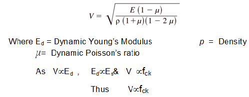
Thus it can be seen from the above equations that, pulse velocity is directly proportional to the compressive strength of concrete.
Procedure
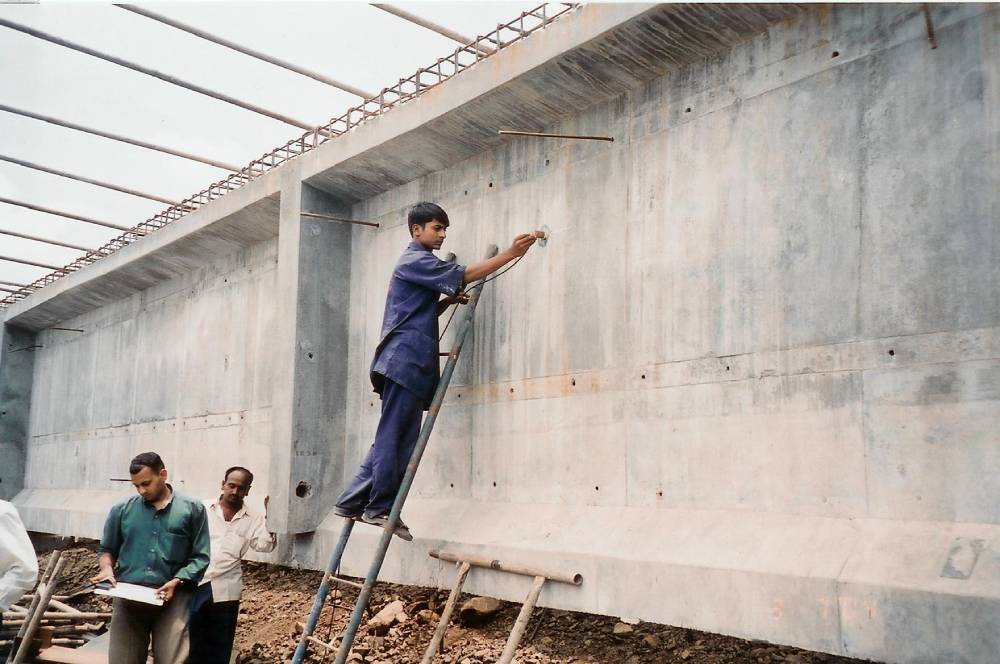
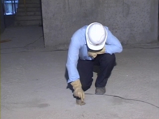
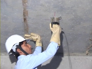
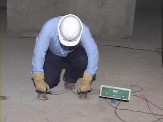
There are three possible ways of measuring pulse velocity :

( cross probing )


( Surface probing )
The Direct & Semi-Direct Transmission is used mainly for predicting the Quality of concrete & Compressive strength &Indirect transmission used assess the quality of surface concrete and measurement of crack depth.
The transducers are placed on the smooth concrete surface to measure the time required for travel. A coupling media such as petroleum jelly, grease are applied to the surface to have good acoustical coupling. The velocity is calculated as
V = L / T
Where, L is the distance between two probes and
T is the time required to travel the distance between two transducers.
If the quality of concrete in terms of homogeneity, strength and uniformity is good then the velocity obtained is higher.
In practice it is convenient to establish the relation between strength of cube and pulse velocity. Co-relation charts are prepared based on the above relationship by testing sufficient numbers of cubes under various conditions and for various mix designs. This Co-relation charts also has to applied proper modifications / correction factor for various influencing conditions such as Age, Grade of concrete, Moisture content, Type of aggregate, water cement ratio, Stress, temperature, reinforcement, Method of probing etc.
At Construction Diagnostic Centre (CDC), we have carried out an extensive research on (on more than 75,000 cubes and core samples) quality & strength assessment and it has been observed that, the quality gradation as per 516 – Part 5 Sec 1- 2018 is misleading, as it do not discriminate between low strength concretes such as M-15 , M-20 and very high strength concrete of more than M-40, it gives same qualitative assessment for any grade of concrete. Further IS standard do not mention any quality assessment norms for semi direct and in-direct test methods. We recommend to grade the quality of concrete as per below given table –
| Gradation of Quality of concrete ( as per CDC ) – Direct & Semi Direct velocity Km/Sec. |
|---|
| Quality of Concrete | Grade< M-15 | M-20 to M-25 | M-30 to M-35 | >M-40 |
| Excellent | Above 4.250 | Morethan 4.400 | Morethan 4.600 | Morethan 4.900 |
| Good | 3.500 to 4.250 | 3.750 to 4.400 | 3.900 to 4.600 | 4.150 to 4.900 |
| Medium | 3.000 to 3.500 | 3.400 to 3.750 | 3.600 to 3.900 | 3.800 to 4.150 |
| Doubtful | Below 3.000 | Lessthan 3.400 | Lessthan 3.600 | Lessthan 3.800 |
| Gradation of Quality of concrete ( as per CDC ) – Indirect velocity Km/Sec |
|---|
| Quality of Concrete | Grade<M-15 | M- 20 to M-25 | M-30 to M-35 | >M – 40 |
| Excellent | Above 3.750 | Morethan 3.900 | Morethan 4.100 | Morethan 4.400 |
| Good | 3.000 to 3.750 | 3.250 to 3.900 | 3.400 to 4.100 | 4.650 to 4.400 |
| Medium | 2.500 to 3.000 | 2.900 to 3.250 | 3.100 to 3.400 | 3.300 to 3.650 |
| Doubtful | Below 2.500 | Lessthan 2.900 | Lessthan 3.100 | Lessthan 3.300 |
Ultrasonic Pulse velocity test is being used successfully world over, even on timber members to assess the quality of timber.
At CDC we have carried out extensive research on quality assessment of timber and we recommend to grade the quality of timber as per below given table –
| Gradation of Quality of Timber ( as per CDC ) |
|---|
| Ultrasonic Pulse Velocity test | Good | Medium | Doubtful |
| Velocity – Direct method – Km/sec | 1.80 & above | 1.30 to 1.80 | < 1.30 |
| Velocity – Semidirect method – Km/sec. | 2.00 & above | 1.45 to 2.00 | <1.45 |
| Velocity – Indirect method* – Km/sec. | 3.70 & above | 3.20 to 3.70 | < 3.20 |
Moisture Content : –
The pulse velocity through saturated concrete is higher by about 2 to 10 % than dry concrete. For high strength and well-compacted concrete the influence is less as against low strength and less compacted concrete.
Stress :
At higher stress level significant reduction in pulse velocity is observed. Hence it is recommended to establish the correction factor for stress
Type of Aggregate : –
For aggregate having higher specific gravity pulse transmission is slower.
Type of Mix & water / cement ratio : –
With the change in mix proportion the % change in velocity is less as compared with the % change in compressive strength. For change in w/c ratio, % change in velocity is comparable with % change in the strength.
Reinforcement : –
The pulse velocity through steel is about 5.9 Km/sec. as against 3 to 4.5 Km/sec. of concrete. Thus it can be seen that, for weaker concrete the effect of reinforcement is more than for higher strength concrete. As far possible reinforcement shall be avoided while selecting the test point.
If the axis bar is parallel to the pulse path ( which is a rare case, may be foundations ), the increase in velocity may be to the extent of 5 to 20 % depending on the bar size and the location of bar from the path of the pulse.
Path length :-
The minimum path length is governed by the frequency of the transducers
Min. Path length ( mm ) = Velocity (m/Sec) / Natural frequency of transducers (kHz)
| Natural frequency of transducers kHz |
Minimum path length (mm) For concrete with | |
|---|---|---|
| V = 3.5 Km/sec | V = 4.5 Km/sec. | |
| 150 | 23 | 30 |
| 100 | 35 | 45 |
| 50 | 70 | 90 |
| 20 | 175 | 225 |
There is no significant drop in velocity up to 3.0 m path length. For 3 m to 6 m path length, reduction of 5 % in pulse velocity has been reported. For higher lengths it is recommended to use amplifiers to compensate the loss of signal
Type of Cement : –
It has observed by the author that, the pulse velocity does not have any significant effect with the different grades and types of cement.
Application
The ultrasonic pulse velocity method is used to assess
- The homogeneity of the concrete
- The presence of cracks, voids and other imperfections, depth of crack
- Changes in the structure of the concrete which may occur with time
- The quality / compressive strength of concrete of one element in relation to another element / standard requirement
- The values of dynamic elastic modulus of concrete
Some Observations & Recommendations
Ultrasonic pulse velocity has been found to be a valuable and reliable method of detecting interior of concrete member in truly a non destructive way
If the data about factors influencing pulse velocity as stated above is not available , then, the assessment of compressive strength will have limitations. The accuracy of the strength prediction by this method at about 95 % confidence level is about ± 15 – 20 % depending upon the concrete mix design data available and the correction factors applied. It is recommended to use this test in combination with rebound hammer & core test for new concrete and with core test for old concrete.
Recommendations –
- Avoid Indirect method wherever possible especially for slabs and walls. Reliability of Indirect method is less. Always perform test by Direct or Semi- direct method
- Normally it is observed that the if the columns are casted with 2.4 m height, then the UPV at bottom portion of column is always more ( by @ 15 to 20 % ) compared to the UPV of top portion.
- But columns casted with ‘window’ system or a concrete drop height of less than 1.5 m, the UPV reading at top & bottom are almost same
- Good surface contact is essential
- Stress in concrete affects the UPV and interpretation requires sufficient data and skill
- Surface defects – such as cracks / voids may reduce the velocity, misleading as if the entire concrete quality is doubtful
- UPV of foundations – Should be away from the reinforcement. Apply corrections factors if necessary
- Collect site data – Type of aggregate, moisture content, Mix proportion
- While measuring the depth of crack – Reference point shall be totally crack free
- Normally the slab direct UPV values are higher than the adjacent beam casted with same concrete
- To increase the accuracy level of strength prediction with UPV, co-relation site concrete cubes / cores with UPV
- Strength estimation accuracy reduces for high strength concrete ( > M – 40 ). It is recommended to combine Core test ( Extractatleast 15 % core samples of UPV test locations ) along with UPV test.
- For dense concrete UPV will reduce and not increase. Especially for a very high density aggregate like Hematite the UPV is lower.

