Corrosion is an electrochemical process. For corrosion of steel reinforcement to occur in concrete, an ionic current (a flow of ions) must pass between anodic and cathodic regions of the concrete. The electrical resistivity of the concrete affects the ionic flow and the rate at which corrosion can occur; a higher concrete resistivity decreases the current flow. An empirical relationship between corrosion rate and concrete resistivity has been derived from measurements on actual structures
The resistivity of a given structure exposed to chloride load gives information about the risk of early corrosion damage, because generally a low concrete resistivity is correlated to rapid chloride penetration and to a high corrosion rate.
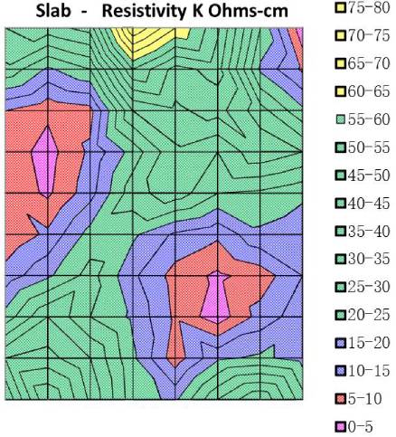
The electrical resistivity of concrete is a materials property that may be useful for monitoring and inspection of concrete structures with regard to reinforcement corrosion. Generally a low concrete resistivity is correlated to rapid chloride penetration and to a high corrosion rate. In addition resistivity mapping may show the most porous spots, where chloride penetration is likely to be fastest and future corrosion rates will be highest.
Resistivity does not show whether steel in concrete is in an active state of corrosion or not. That information must be obtained in another way, from chloride analysis, carbonation depth measurement, potential mapping, and visual inspection of the steel. If the steel is actively corroding, resistivity measurements may give additional information: it may show where in the structure corrosion may be strongest.
Four probes
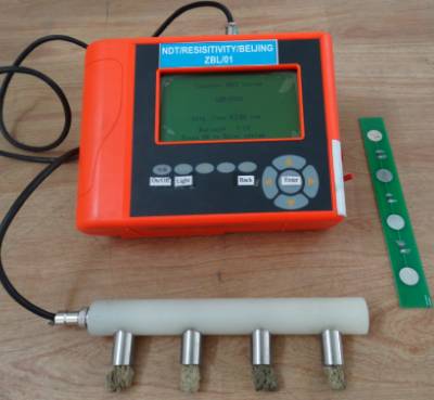
Concrete electrical resistivity can be obtained by applying a current into the concrete and measuring the response voltage.
On-site electrical resistivity of concrete is commonly measured using four probes in a Wenner array. The reason for using four probes is the same as in the laboratory method – to overcome contact errors. In this method four equally spaced probes are applied to the specimen in a line. The two outer probes induce the current to the specimen and the two inner electrodes measure the resulting potential drop. The probes are all applied to the same surface of the specimen and the method is consequently suitable for measuring the resistivity of bulk concrete in situ.
The resistivity is given by:

V is the voltage measured between the inner two probes (measured in volts, V)
I is the current injected in the two outer probes (measured in amps, A)
a is the equal distance of the probes (measured in meters, m).
- To assess the (range of) value(s) of the concrete resistivity of a particular structure, in order to estimate the risk of corrosion in case passivation will be (or has been) lost
- To locate the most permeable parts of a structure, in order to define further investigations or protective measures
- To locate spots with the most severe exposure to water and dissolved aggressive species
- To help design systems for cathodic protection and other electrochemical treatments
- Quality control of concrete in the production phase
Interpretation of Results –
| Resistivity (K Ohm-cm) | Risk of Corrosion |
|---|---|
| Greater than 100 | Negligible |
| 50 to 100 | Low |
| 10 to 50 | Moderate |
| Less than 10 | High |
| Resistivity (K Ohm-cm | Corrosion Rate |
|---|---|
| Greater than 200 | Very Low |
| 20 to 200 | Low |
| 10 to 20 | Low to moderate |
| 5 to 10 | High |
| Less than 5 | Very High |
Factors Affecting Resistivity test & Limitations –
- Resistivity is increased by –
- lower water to cement ratio (w/c),
- longer curing times (hydration) or
- by the addition of reactive minerals such as blast furnace slag, fly ash and/or silica fume.
- Carbonation ( In case of OPC )
- Resistivity of cover concrete is decreased by –
- Increasing concrete porosity
- Increasing temperature
- Increasing chloride content
- Resistivity of concrete increases when the concrete is drying out and when the concrete carbonates
- Concrete with calcium nitrite admixture ( Set accelerator ) indicate lower resistivity values
- Lime water curing on average reduces resistivity by 10%.
- Reinforcing steel can cause a “short circuit” path and give a misleadingly low reading
- The resistivity of a concrete with granite aggregate has higher than with limestone
- Increase in aggregate content will increase the electrical resistance
- A higher temperature causes the resistivity to decrease