Ground-penetrating radar (GPR) is a geophysical method that uses radar pulses to image the subsurface. This nondestructive method uses electromagnetic radiation in the microwave band (UHF/VHF frequencies) of the radio spectrum, and detects the reflected signals from subsurface structures.
GPR uses high-frequency (usually polarized) radio waves, usually in the range 10 MHz to 3.0 GHz. A GPR transmitter emits electromagnetic energy into the ground or materials like concrete, masonry etc. to be inspected. When the energy encounters a buried object or a boundary between materials having different permittivities, it may be reflected or refracted or scattered back to the surface. A receiving antenna can then record the variations in the return signal. GPR methods implement electromagnetic energy and energy may be reflected at boundaries where subsurface electrical properties.
The electrical conductivity of the material, the transmitted center frequency, and the radiated power all may limit the effective depth range of GPR investigation. Increases in electrical conductivity attenuate the introduced electromagnetic wave, and thus the penetration depth decreases. Because of frequency-dependent attenuation mechanisms, higher frequencies do not penetrate as far as lower frequencies. However, higher frequencies may provide improved resolution. Thus operating frequency is always a trade-off between resolution and penetration
Ground Penetrating Radar (GPR) is an accepted electromagnetic evaluation technique used for the transportation infrastructure and a variety of other applications including concrete inspection, utility detection, geology and archeology. A well-established and accepted application of GPR is the accurate condition assessment of bridge decks as well as other reinforced concrete structures.
GPR Data Collection (in concrete)
The GPR has many surveying abilities, including:
- 3D imaging of shallow and deep rebars in concrete;
- Inspection of concrete for location of voids
- Inspection of concrete thickness, integrity
- 3D imaging of pre-tension and post-tension cables;
- Inspection and analysis of old structures and monuments;
- Inspection of walls and floors for the location of pipes, objects, caches, etc..
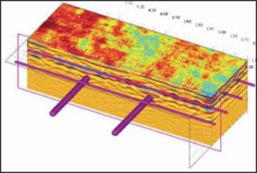
To locate objects such as rebar, conduits and post-tension cables imbedded in concrete a high frequency GPR ( 1500 to 3000 Mhz) system is used. The data can be collected in simple line scans to determine the thickness of concrete or in a grid format which will produce a map of any targets located in the concrete. Using this method we can look at virtual slices in the image to determine the depth of the objects and create a 3D map of the image.


GPR Data Analysis
GPR waves travel through many different materials. Different types of soil, concrete, fill material, debris, and varying amounts of water saturation all have different dielectric and conductive properties that affect the GPR waves, and thus GPR data interpretation. Although the data images are displayed on the screen they still require someone with field experience to interpret them in order to accurately determine the findings.
The high frequency ground-coupled antenna provides excellent resolution of the reinforcing steel. The acquired GPR data was processed by an advanced post processing software GRED HD 3D. The software presents a 2D / 3D view of the subsurface.
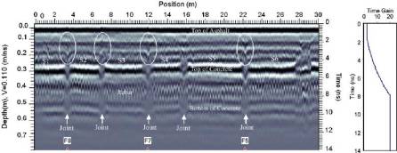
Rebar appear in the GPR data as small hyperbolas. These hyperbolas occur because the antenna transmits energy in a conical pattern, and consequently, receives reflections from the rebar at decreasing two-way travel times as it approaches the rebar, then increasing two-way travel times after the antenna passes over the rebar.
Rebar locations are evident in the unprocessed data as well as obvious areas of deterioration where rebar reflections are weak. Areas of the bridge deck exhibiting weak reflection amplitude values are typically indicative of deterioration. These weaker reflections can be due to several factors, including elevated chloride content, concrete degradation or corrosion of the rebar, which all attenuate the radar signal In most cases, the bottom of the bridge deck is also visible in the GPR data and appears as a white-black-white horizontal band
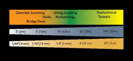
How Deep Can It Go?
This is probably one of the most commonly asked questions. In most cases an estimated depth range can be determined with accuracy based upon the subsurface material and the frequency of the GPR antenna. For applications requiring higher resolution, such as locating rebar or conduits in concrete, a higher frequency GPR system (1,500 to 3000 MHz) is used. This will give high resolution detail for down to approximately 250 – 600 mm in depth. Applications which require deeper penetration in ground soil requires a lower frequency (12.5 MHz to 500 MHz). Depending on the subsurface material the depth range can be from a few inches to thousands of feet (as indicated in the chart).

Limitations
- If the differences in properties of material are small or their changes are gradual then returning signals are difficult to interpret sometime impossible.
- In moist soil, clay or soil with high mineral contents, signal penetration is very less
- Considerable expertise is necessary to effectively design, conduct, and interpret GPR surveys
- GPR does not measure diameter of objects, but just their location.
- Bottom of slab is sometimes not easy to see in slab-on-grade situations. This is due to the interference of the wire mesh and the weak reflection from the concrete-gravel base interface.
- GPR very difficult in some conditions like, freshly-poured concrete, concrete containing metal fibers, fine-mesh screenings beneath tile
- Spacing between rebars should not be less than 50 to 70 mm
- The voids smaller than 50 mm may not be detected
- Relatively high energy consumption can be problematic for extensive field surveys.